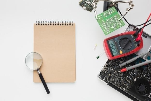
CDI Electronics Troubleshooting⁚ A Comprehensive Guide
This guide provides a structured approach to diagnosing and resolving issues with CDI (Capacitive Discharge Ignition) systems; It covers various troubleshooting techniques, from basic voltage checks to advanced signal tracing. Safety precautions are emphasized throughout, ensuring safe and effective repairs.
Understanding CDI Systems in Outboard Motors
CDI (Capacitive Discharge Ignition) systems are electronic ignition systems commonly used in outboard motors. Unlike older points-based systems, CDI utilizes a capacitor to store electrical energy and then rapidly discharge it to the spark plug, creating a high-voltage spark for ignition. This results in a more reliable and consistent spark across a wider range of engine speeds. The CDI unit itself is a compact electronic control module that receives signals from various engine sensors, such as the crankshaft position sensor. Based on these signals, the CDI unit precisely times the spark delivery for optimal combustion. Understanding the basic components and operational principles of a CDI system is crucial for effective troubleshooting. Key components include the CDI unit itself, the ignition coil, the spark plugs, and various wiring harnesses connecting these parts. Malfunctions within any of these components can lead to ignition problems, highlighting the importance of systematic diagnostics.
Identifying Common CDI Failure Symptoms
Recognizing the symptoms of a failing CDI unit is the first step in effective troubleshooting. Common indicators include a complete lack of spark, resulting in a non-starting engine. Intermittent sparking, characterized by the engine occasionally firing but failing to run consistently, is another frequent symptom. This erratic behavior often points towards a problem within the CDI unit or its associated wiring. Engine performance issues, such as misfires or a rough running engine, can also be attributed to a malfunctioning CDI. These misfires may be consistent or intermittent, depending on the nature of the CDI failure. Difficulty starting the engine, especially after it has been running for a period of time, is another tell-tale sign. This suggests a potential problem with the CDI’s ability to generate sufficient voltage under load. Finally, unusual noises emanating from the CDI unit itself, such as buzzing or clicking sounds, should raise immediate concern and warrant further investigation. These auditory cues might indicate internal component failure within the CDI module.

Basic CDI Testing Procedures⁚ Voltage and Continuity Checks
Begin CDI testing with a visual inspection, checking for any obvious signs of damage like burned components or loose connections. Then, use a multimeter to measure the voltage at the CDI unit’s input terminals. The voltage should match the engine’s specified operating voltage; deviations indicate a problem with the power supply or battery. Next, test for continuity between the CDI terminals using the multimeter’s continuity setting. This checks for open circuits that prevent proper signal flow. Ensure the ignition switch is in the “off” position during these tests to prevent accidental shocks or damage. If the CDI receives the correct voltage but fails the continuity test, it suggests an internal fault within the CDI unit itself. Remember, always disconnect the negative battery terminal before performing any electrical tests to prevent injury. Consult a wiring diagram for your specific outboard motor model to accurately identify the correct terminals for testing and to avoid damaging other components. Proper safety procedures are crucial throughout the testing process. Accurate voltage and continuity readings can pinpoint a faulty CDI unit or other problems in the ignition system.
Advanced Diagnostics⁚ Signal Tracing and Component Testing
If basic checks don’t reveal the CDI issue, more advanced diagnostics are necessary. Signal tracing involves using an oscilloscope to observe the electrical signals within the CDI system. This allows you to pinpoint where the signal is interrupted or distorted. A malfunctioning signal could indicate problems with the pick-up coil, stator, or other components in the ignition circuit. Component testing involves individually examining each component of the CDI system, such as the ignition coil and the power pack, to identify the faulty part. This often requires specialized tools and knowledge of electronic circuits. A faulty ignition coil, for example, may show a lack of sufficient voltage or current output. The oscilloscope allows you to examine the waveform of the signal, providing insights into the nature and timing of the spark. Using a schematic diagram for your specific outboard motor is essential for identifying the correct components and their connections. Remember to always disconnect the battery’s negative terminal before working with any electrical components, and consult a repair manual for specific procedures and safety precautions related to your outboard motor.
Troubleshooting Specific CDI Issues⁚ No Spark, Intermittent Spark, etc.
Addressing specific CDI problems requires a systematic approach. A complete lack of spark usually points to a faulty CDI unit, a broken wire in the ignition system, or a problem with the kill switch circuit. Start by visually inspecting all wiring and connections for damage or corrosion. Intermittent spark, on the other hand, often suggests a loose connection, a failing CDI unit, or moisture affecting the ignition system. Check the spark plug cap and wire for cracks or damage. A weak spark might indicate a low battery voltage, a faulty coil, or a problem within the CDI itself. If the engine runs for a short period and then stops, suspect issues with the stop circuit. Testing the stop circuit involves checking the stop switch, wire connections, and the CDI unit’s stop circuit functionality. Remember, always consult your engine’s specific service manual for detailed troubleshooting steps and diagrams. Improper diagnostics or repairs can lead to further damage or even personal injury. Systematic testing, starting with the simplest checks, will significantly aid in identifying the root cause.
CDI System Voltage Requirements and Battery Health
The CDI system’s proper operation hinges on a stable and sufficient power supply. Most CDI units require a nominal voltage of 12V DC, although this can vary depending on the specific system. Voltages outside the acceptable range, whether too low or too high, can damage the CDI unit and other components. A low voltage often manifests as a weak or intermittent spark, while excessively high voltage can lead to component failure. Regularly check your battery’s voltage using a multimeter. A fully charged battery should read around 12.6V. Low voltage might indicate a weak battery, a faulty charging system, or excessive parasitic drain. A high voltage could suggest a problem with the voltage regulator. It’s crucial to use a battery appropriate for your engine and ensure its terminals are clean and securely connected. Avoid using maintenance-free batteries, as these may not provide the necessary power consistency. Regular battery maintenance, including terminal cleaning and testing, is essential for reliable CDI system performance and engine operation.
Importance of Proper Wiring and Connections
The reliability of your CDI system heavily depends on the integrity of its wiring and connections; Loose, corroded, or damaged wires can disrupt the electrical signals necessary for ignition, leading to a range of problems, from weak sparks to complete engine failure. Regularly inspect all wiring and connections for any signs of wear and tear, corrosion, or damage. Pay close attention to the connections at the CDI unit itself, the spark plugs, and the kill switch. Ensure all connections are clean, tight, and free of corrosion. If corrosion is present, carefully clean the connections using a wire brush and electrical contact cleaner. Replace any damaged or frayed wires promptly with appropriately sized and rated replacements. Improper wiring, such as incorrect polarity or short circuits, can severely damage the CDI unit and other components. Always consult a wiring diagram specific to your engine model to ensure correct wire routing and connections. Remember, using appropriate wire sizes to handle the current is vital for optimal system performance and to prevent overheating and potential fires.
Stop Circuit Troubleshooting⁚ Identifying and Fixing Issues
The stop circuit in your outboard motor’s CDI system is crucial for safely shutting down the engine. Problems within this circuit can manifest as an engine that won’t shut off, even when the key is turned, or an engine that fails to start due to a persistent kill signal. Troubleshooting begins with visually inspecting the stop switch and its wiring. Look for loose connections, corrosion, or broken wires. A multimeter can help test the continuity of the stop circuit. With the engine off, disconnect the stop wire at the CDI unit. Check for continuity between the stop wire and ground. If continuity exists, the switch or wiring might be faulty. If there’s no continuity, the issue may lie within the CDI unit itself or another part of the circuit. Testing the stop switch involves checking for continuity between its terminals in the “on” and “off” positions. Replace any faulty switches or repair damaged wiring. If the issue persists after checking the switch and wiring, further investigation of the CDI unit or other components in the stop circuit might be necessary. Always consult your engine’s wiring diagram to understand the complete stop circuit configuration for your specific model.
Using CDI Electronics Troubleshooting Guides and Manuals
Effective CDI system troubleshooting heavily relies on utilizing the appropriate resources. CDI Electronics provides comprehensive troubleshooting guides and manuals specific to their products, offering detailed diagrams, component specifications, and step-by-step procedures. These resources are invaluable for identifying potential issues, understanding system functionality, and performing accurate diagnostics. Before starting any troubleshooting, locate the specific manual for your CDI unit model. This manual contains detailed wiring diagrams, component layouts, and specific troubleshooting steps for your particular system. The manual might also contain diagnostic flowcharts, guiding you through a series of tests to isolate the problem area. Pay close attention to safety precautions highlighted within the manual, as working with electrical systems requires careful attention to avoid injury. If you encounter unfamiliar terminology or procedures, consult online resources or seek guidance from experienced technicians. Remember that incorrect procedures could damage components and void warranties. By using these official resources responsibly, you can significantly increase the efficiency and accuracy of your CDI troubleshooting efforts.

Safety Precautions When Working with CDI Systems
Working with CDI systems involves high voltage and potentially dangerous electrical components. Prioritize safety throughout the troubleshooting process. Always disconnect the battery’s negative terminal before commencing any work on the CDI system. This prevents accidental shocks and short circuits. Never touch high-tension leads (spark plug leads) while the engine is running; severe electrical system damage can result. Use insulated tools and wear appropriate safety gear, including safety glasses and gloves, to protect yourself from potential hazards. When testing components, ensure the multimeter is set to the correct voltage range to avoid damaging the meter or the CDI unit. Consult the CDI unit’s manual for specific safety guidelines and recommended procedures. If unsure about any step, seek assistance from a qualified marine mechanic or CDI specialist. Improper handling of CDI components can lead to serious injury or equipment damage. Remember that even with the battery disconnected, residual voltage may remain in capacitors; discharge these before handling. Thoroughly understand the system’s wiring diagram before making any connections or adjustments to prevent accidental shorts or incorrect configurations. Always double-check your work to ensure all connections are secure and properly insulated.
